
A pump’s running power does not tell you whether a battery inverter can start it. Starting capability depends on the current demanded during acceleration, how long that demand lasts, the AC voltage maintained by the inverter, and the battery system’s ability to supply the corresponding DC load. A large battery energy rating cannot answer all of those questions.
For motor starting on a battery inverter, require a load-specific assessment rather than a match between two headline watt ratings. The evidence should cover the actual starter, driven machine and operating conditions. Starting an unloaded motor in a factory demonstration does not establish performance for a loaded pump at the customer’s site.
Read the motor rating correctly
A motor nameplate may state mechanical output power. Electrical input also depends on efficiency and power factor. Schneider Electric’s induction-motor guide explains this distinction and addresses starting current separately. That is why an inverter selection based solely on the motor’s output kW can miss the electrical requirement.
Request the motor’s rated voltage, phases, frequency, full-load current and available starting-current data. Then identify direct-on-line, soft-starter or variable-frequency-drive operation. Changing the starting method may alter the load profile, but it also introduces a separate device whose compatibility and settings must be reviewed.
| Input | Why the buyer needs it | Evidence source |
|---|---|---|
| Motor and driven-machine identification | Distinguishes the electrical machine from its mechanical duty | Nameplates, datasheets and process description |
| Starting method | Defines the equipment actually connected to the inverter | Starter or drive model and approved configuration |
| Starting current and duration | Checks the demand against the inverter’s time-dependent limit | Manufacturer data or a competent measurement |
| Mechanical starting condition | Shows whether the demonstration represents site operation | Load, pressure, inertia and restart conditions |
| Other simultaneous loads | Establishes remaining source headroom | Critical-load schedule and start sequence |
When data are missing, mark the item unresolved. Do not replace it with a generic surge multiplier and describe the result as a verified design. A preliminary estimate can guide further investigation only when its assumptions are stated and its status is clear.
A peak rating needs a time axis
Inverter specifications may distinguish continuous output, short-duration overload and instantaneous protection. Ask which quantity is stated in watts, volt-amperes or amperes, under which temperature and battery conditions, and for what duration. A peak value without those conditions is not a usable motor-starting guarantee.
Victron’s inverter protection manual describes a product-specific example in which motor inrush can cause output voltage reduction or an overload shutdown. It illustrates the mechanism, not a performance prediction for an HMX inverter.
Voltage matters because a motor may fail to accelerate if the source cannot maintain an adequate starting condition. A demonstration in which the inverter remains on but the motor stalls is not a successful start. Agree the process outcome, electrical limits and allowed start sequence before the test.
For a backup installation, compare this requirement with the island capability described in our battery black-start and backup guide. Being able to energise a bus and being able to start a particular motor on that bus are separate acceptance items.
Follow the demand back to the battery
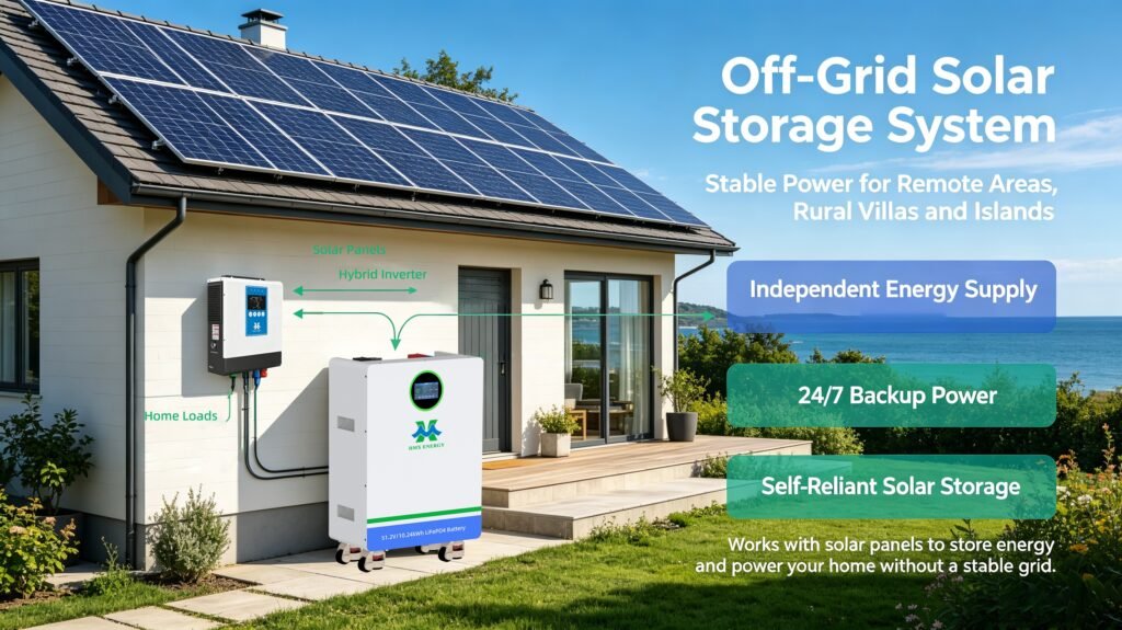
The inverter’s overload capability is useful only if the DC source supports it. Review battery discharge limits, BMS time conditions, allowed SOC and temperature range, connectors, conductors and protective devices. A current limit imposed upstream can prevent a start even when the inverter’s own brochure appears adequate.
Victron’s DC wiring reference connects cable selection with current and voltage drop. Project conductor and protection selection must still follow the actual equipment manuals and local electrical requirements, not a copied example table.
A useful test distinguishes battery-terminal voltage from inverter-input voltage. Their difference helps identify the supply path’s behaviour during the event. Qualified personnel must use suitable instruments and a safe measurement procedure; improvised live probing is not an appropriate customer acceptance exercise.
| Recorded channel | What it helps distinguish | Supporting context |
|---|---|---|
| AC current and voltage over time | Demand profile and source response | Sampling capability and start command timing |
| Battery and inverter DC voltage | Battery sag versus supply-path drop | Measurement locations and battery condition |
| Battery limit and BMS events | Source restriction versus inverter overload | Firmware, SOC and temperature records |
| Motor acceleration or process feedback | Electrical energisation versus a completed start | Actual mechanical load and success criterion |
| Other connected loads | Standalone demonstration versus site duty | Load schedule and permitted sequencing |
Repeated starts deserve a different test from a single demonstration
A process may restart a pump repeatedly, start several motors in sequence, or require recovery after a short outage. Ask the supplier to review those duties explicitly. The interval between starts, thermal state and battery conditions can differ from a single start on a freshly charged system.
Where sequencing is permitted, make it part of the operating design and customer handover. Where simultaneous starting is essential, do not quietly replace the requirement with a staggered demonstration. Any mitigation should be agreed with the process owner, not introduced after equipment fails a test.
When selecting battery storage for inverter-backed loads, check both usable energy and discharge capability. The storage duration discussion should not hide a current-limit problem that can occur immediately.
A clear go/no-go record beats a larger headline rating
Use the off-grid battery sizing framework for the energy and reserve calculation, and attach the motor-starting assessment as a separate design input. The accepted load list should name the motor, starter, battery configuration and operating constraints.
Release the design only when the required starting duty fits the documented AC and DC capability, or when an approved test demonstrates the complete combination under representative conditions. A bigger advertised inverter peak is not a substitute for that evidence.