
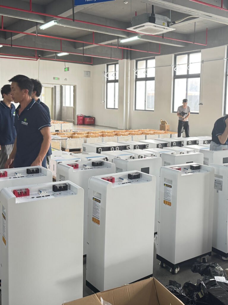
Replacing a lead-acid solar battery bank with LiFePO4 can change more than the enclosure and energy capacity. The charger may use an unsuitable recovery stage, the inverter may interpret voltage differently, and legacy DC loads may remain connected after the battery’s normal operating limits are reached. A nominal voltage match is only the start of a retrofit review.
For installers serving off-grid homes, farms and small businesses, approve the charging and load-control arrangement before ordering the pack. The objective is a documented replacement system, not a battery that happens to accept charge on the day it is connected.
Inventory every charging source before choosing the battery
List the solar controller, inverter/charger, generator-fed charger and any auxiliary source. Identify model numbers, firmware, active profiles and the means of limiting or stopping charge. A site with several chargers can have one correctly configured unit and another that still follows the old lead-acid routine.
When reviewing low-voltage LiFePO4 battery options, request the manufacturer’s complete charging requirements and approved series or parallel arrangements. A product described for one nominal voltage should not be assumed suitable for an existing bank configuration without that review.
Obtain the existing settings before changing them. An installer needs to know whether equalisation, reconditioning, temperature compensation or a recovery routine can occur automatically, not just which mode appears on the current screen. Check whether a restart, replacement controller or reset can restore the old settings.
Do not carry a lead-acid recovery stage into the lithium proposal
Victron’s Blue Smart IP65 charging manual describes reconditioning as an optional lead-acid stage and treats lithium charging separately. This is a useful product-specific illustration of why the whole profile matters. The correct configuration for a different charger and pack must come from their own documentation.
Texas Instruments’ LiFePO4 Design Considerations application note discusses chemistry-specific charging and the relationship between voltage and SOC. A menu option labelled “lithium” does not necessarily describe every permitted pack profile. Obtain the target voltage, current, termination and restart requirements for the exact replacement battery.
| Existing function | Question before reuse | Required evidence |
|---|---|---|
| Equalisation or reconditioning | Can it occur automatically or after a reset? | Approved replacement profile with prohibited stages excluded |
| Temperature-based voltage adjustment | Does it match the lithium pack’s instructions? | Model-specific thermal and voltage configuration |
| Charge-current setting | Does the sum of active sources respect pack limits? | Combined-source operating review |
| Charge termination and restart | Can the charger follow the battery’s permitted sequence? | Profile documentation and functional evidence |
| Restart after battery disconnect | Does the charger resume safely and correctly? | Approved BMS-stop and recovery test |
The BMS must coordinate with the equipment that uses the bank
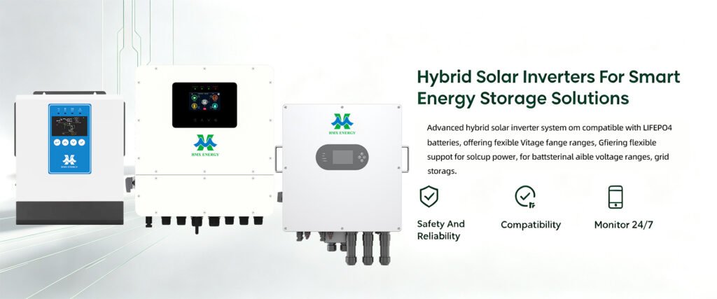
The BMS may restrict charging or discharging before the normal energy-management routine would stop. Ask how the solar controller and inverter respond to those limits. If the integration uses a communication protocol, verify the approved combination and message behaviour. A physical CAN or RS485 connection is not sufficient proof.
The Victron Lithium Smart operating instructions distinguish approved charging behaviour and warn about residual loads after a low-voltage shutdown. These are model-specific instructions, but they show why a retrofit needs a recovery and unattended-storage policy rather than reliance on a protective trip.
For an HMX solar inverter proposal, ask the supplier to confirm the intended battery mode, BMS interface and firmware. If a legacy inverter cannot follow the required limits, price the necessary controller or inverter change instead of calling the new pack a drop-in replacement.
Revisit legacy DC loads and the physical current path
Old installations may include direct DC lighting, communications equipment, pumps or auxiliary converters. Identify their permitted input voltage and what happens when the battery disconnects or its output recovers. Some loads may have been added without appearing on the original drawing.
Assess the DC protection, conductors, terminals and isolation arrangement for the replacement configuration. Do not reuse a fuse or cable merely because it carried the previous bank’s normal current. The designer needs to review the new operating duty and fault conditions with the relevant equipment data.
The mechanical review matters too: mounting, access, environmental conditions and service clearances can differ. A battery installed where a lead-acid bank stood may still require different installation provisions. Keep the new manufacturer’s instructions with the as-built record.
Make the acceptance test prove normal control and restricted operation
Agree a commissioning plan with qualified personnel and the suppliers. Test representative operation and the approved response to charge or discharge inhibition without deliberately abusing the cells. A charger display that says “full” is not evidence of suitable BMS coordination.
| Check | Record expected | What it prevents |
|---|---|---|
| Final equipment and profile | Models, firmware and approved settings export | Untraceable changes to legacy defaults |
| Concurrent charging sources | Measured operation and implemented current limits | Several individually acceptable chargers exceeding a combined limit |
| BMS inhibition and recovery | Approved control sequence and resulting states | Repeated stop/restart cycling or uncontrolled recovery |
| Legacy DC loads | Compatibility, control and reconnection behaviour | Unexpected load loss or unsuitable supply voltage |
| Customer standby procedure | Documented storage and recovery instructions | Residual drain while the site is unattended |
Quote the retrofit boundaries plainly
The quotation should state which existing equipment is retained, which is replaced and which requires further verification. Include commissioning and customer instruction, not just the battery price. If the legacy charger documentation is unavailable, label that as an unresolved approval item rather than assuming the closest-looking profile is suitable.
Use our off-grid battery sizing guide to revisit loads, replenishment and reserve once the compatibility review is complete. More usable energy can be valuable, but it cannot compensate for a charger or control arrangement that the new battery is not approved to use.
A sound retrofit proposal answers how the pack is charged, how limits reach each source and load, and how the owner recovers from an interruption. Those answers are what turn a replacement battery into a serviceable system.