
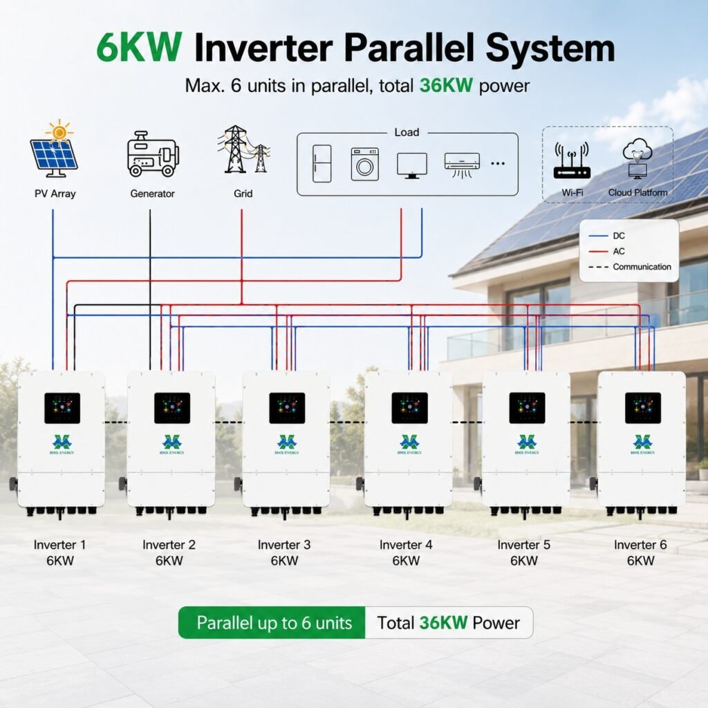
Parallel inverter systems can add capacity and create service flexibility, but they also add communication, protection and current-sharing requirements. A group of units is not automatically a redundant system if one common battery, bypass or control failure can stop the site.
The buyer should compare complete architectures rather than multiplying one inverter’s rating by the unit count.
A related HMX reference is the 6.5kW–12kW 48V inverter platform. Use it to frame the next supplier discussion, then record project-specific deviations before ordering.
Parallel capacity is not automatic redundancy
These are the practical objections and failure modes most likely to stop approval, delay commissioning or create an avoidable service call for Off-grid installers and residential/commercial EPCs.
- Unequal DC cable resistance causes poor current sharing.
- A common battery, bypass or controller remains a single point of failure.
- Mixed firmware or phase settings block commissioning.
Questions the buyer should ask before approval
- Can one unit be isolated while the others continue safely?
- What approved unit count and phase arrangement apply?
- How are load share and fault isolation tested?
Parallel operation adds control ownership as well as hardware. Use the BMS, PCS and EMS interface framework to identify the source of truth for power commands, protection limits, alarms and recovery after communication loss.
Direct answer: Use only parallel combinations approved by the manufacturer. Define phase arrangement, maximum unit count, shared-battery rules, AC protection, bypass behavior and firmware compatibility.
Research review date: 30 September 2026. Quantitative statements are tied to the linked source and should be rechecked if procurement occurs later.
For the final evidence review, use IEC 62109-2 inverter safety scope as a source check. IEC 62109-2 addresses safety requirements for photovoltaic inverters, including protection against electrical, thermal, fire and mechanical hazards.
Compare single-point failures before adding units
For Off-grid installers and residential/commercial EPCs, the first task is to turn the intended service into measurable inputs and acceptance limits. The following table keeps the decision tied to evidence instead of a broad product label.
| Criterion | Single larger inverter | Parallel inverter group |
|---|---|---|
| Equipment count | Fewer power units | More units and communication links |
| Expansion | May require replacement or second system | Possible within approved parallel limit |
| Service | One unit can be a single point of failure | Capacity may reduce after one unit is isolated |
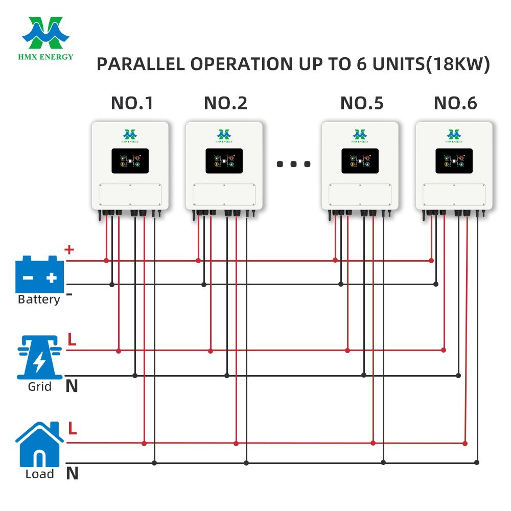
| Wiring | Simpler AC/DC arrangement | Current sharing and equal cable paths matter |
| Commissioning | One configuration | Unit roles, addresses and synchronisation |
Buyers defining the initial scope can compare these requirements with HMX’s 16kW IP65 hybrid inverter. The page is a product or project reference; final suitability still requires a written project specification.
For current market and policy context, review NREL PVWatts Calculator. PVWatts estimates grid-connected PV energy production from location and system inputs. It is useful for the PV side of a study, but it does not replace interval-load and outage analysis for battery sizing.
Commission sharing, bypass and loss-of-peer behavior
The commercial offer should state its assumptions, exclusions and measurement boundary. Buyers can then compare systems on the same basis and keep later design changes under document control.
| Commissioning step | Record | Pass condition |
|---|---|---|
| Firmware check | Version on every unit | Approved and consistent combination |
| Address and role | Master/slave or peer settings | No duplicate or missing address |
| No-load start | Voltage, frequency and phase sequence | Stable synchronisation |
| Load step | Power share by unit | Within allowed imbalance |
| Fault isolation | Trip one unit under controlled test | Remaining system follows approved behavior |
Action points for the project team
- Size busbars, breakers and cables for the complete system.
- Keep DC cable lengths and resistance within the approved design.
- Test bypass and generator transfer modes with the parallel group.
- Provide a clear isolation procedure for servicing one inverter.
The technical comparison should also be checked against U.S. DOE BESS procurement checklist. The U.S. Department of Energy checklist separates early project development, technical specifications and interconnection work for commercial lithium-ion systems.
Measure redundancy at the system level
Draw every common component: battery, DC bus, communications, bypass, transformer, switchgear and site controller. A parallel group may continue after one power unit is isolated, but a shared component can still stop the entire site. State the capacity and functions that remain after each credible single failure instead of calling the architecture redundant without qualification.
For a concrete equipment-level review, apply the checks above to the IP21 solar inverters and request confirmation for the intended site conditions and operating mode.
Parallel designs require approved firmware, role or address settings, phase configuration and current-sharing rules. DC and AC conductor length or impedance may need to remain balanced. Protection and busbar ratings must reflect the complete group, including fault contribution and bypass conditions, rather than one inverter multiplied by quantity.
For specification and acceptance work, IEC 60529 IP Code provides an independent reference. IEC 60529 is the reference for enclosure ingress-protection classifications. An IP rating describes tested enclosure protection; it does not by itself approve an installation site.
Commission at no load, balanced load, step load and the expected maximum operating condition. Record unit-by-unit power, voltage, frequency and temperature. Then isolate one unit under a controlled procedure and confirm the response. Provide settings backups and a service method that prevents an isolated unit from being energised unexpectedly.
From analysis to an auditable decision
- Map common components and remaining capacity after each failure.
- Check manufacturer-approved unit count, firmware and phase arrangement.
- Design balanced conductors, protection and bypass for the whole group.
- Test load sharing, fault isolation and restoration during SAT.
Keep an as-built parallel configuration
Compatibility and safety depend on the equipment as installed, not only on a catalogue selection. Preserve model and firmware identifiers, wiring and protection drawings, physical clearances, settings and test conditions. Later service work should begin from this baseline and record every approved change.
The same evidence and acceptance questions can be used when assessing HMX’s Philippines solar-storage project; catalogue information should be reconciled with the controlled quotation and drawings.
- Named equipment, firmware, accessories, cables and communication settings.
- As-built electrical and physical drawings with isolation points identified.
- Commissioning results for normal operation, limits and selected failure states.
- Backups, photographs, change log and a technician recovery procedure.
After service or firmware work, compare the returned system with the approved baseline and repeat affected tests. This makes later troubleshooting faster and prevents an undocumented field change from invalidating a compatibility or safety conclusion.
Related HMX Equipment Video
This equipment video is included because it matches the hardware or setup discussed here. It is supporting visual material, not third-party certification or proof of performance for a different project.
Commissioning Sign-Off
A signed test sheet should record conditions, instruments, firmware, settings, results and open items. Photographs alone are not a commissioning record.