
Coupling choice affects power-conversion paths, equipment boundaries, metering and control. DC coupling can integrate PV and battery behind a common power-conversion stage. AC coupling can add storage beside an existing PV inverter or separate equipment responsibilities.
Neither topology is universally more efficient. Actual performance depends on where energy flows, how often it is converted and what operating mode dominates.
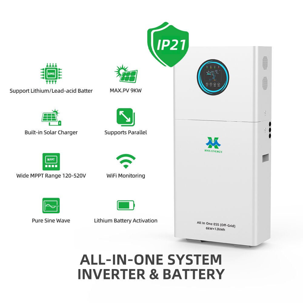
The same evidence and acceptance questions can be used when assessing HMX’s all-in-one ESS range; catalogue information should be reconciled with the controlled quotation and drawings.
Topology should follow the load and operating objective. The home battery sizing guide provides the companion load-side method for separating evening solar shifting, critical-load backup and inverter surge requirements.
Direct answer: Draw the expected energy paths for PV-to-load, PV-to-battery, battery-to-load, grid-to-battery and backup operation. Compare efficiency and equipment limits along each path.
Research review date: 30 September 2026. Quantitative statements are tied to the linked source and should be rechecked if procurement occurs later.
The technical comparison should also be checked against NREL PVWatts Calculator. PVWatts estimates grid-connected PV energy production from location and system inputs. It is useful for the PV side of a study, but it does not replace interval-load and outage analysis for battery sizing.
Choose topology from the dominant energy path
For Solar EPCs, distributors and project developers, the first task is to turn the intended service into measurable inputs and acceptance limits. The following table keeps the decision tied to evidence instead of a broad product label.
| Project question | DC-coupled response | AC-coupled response |
|---|---|---|
| New build or retrofit | Often attractive in integrated new designs | Often practical beside existing PV |
| PV clipping capture | Possible within DC design and battery limits | Depends on AC-side headroom and controls |
| Equipment boundary | Shared hybrid conversion equipment | Separate PV and battery conversion stages |
| Backup design | Requires approved grid-forming arrangement | Requires coordinated microgrid control |
| Metering | DC and AC measurements needed | AC meters at defined points |
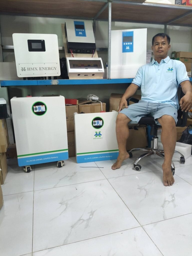
A related HMX reference is the 12kW/30kWh all-in-one ESS. Use it to frame the next supplier discussion, then record project-specific deviations before ordering.
For specification and acceptance work, IEA Electricity 2026 flexibility analysis provides an independent reference. The IEA identifies batteries as a versatile source of short-term power-system flexibility, but the required duration depends on the service being delivered.
Topology decisions that are often made too early
These are the practical objections and failure modes most likely to stop approval, delay commissioning or create an avoidable service call for Solar EPCs, distributors and project developers.
- Retrofit downtime and existing inverter warranties are ignored.
- Efficiency claims use different energy paths and measurement boundaries.
- Backup operation is promised without a grid-forming and transfer design.
Questions the buyer should ask before approval
- Which energy path dominates annual operation?
- Where are export limits and revenue meters located?
- What happens to PV, storage and loads during grid loss?
Compare controls, protection and meter boundaries
The commercial offer should state its assumptions, exclusions and measurement boundary. Buyers can then compare systems on the same basis and keep later design changes under document control.
| Energy path | Losses to include | Control check |
|---|---|---|
| PV to load | PV conversion and site wiring | Export and load priority |
| PV to battery | DC/DC or AC/DC path | Charge limit and curtailment |
| Battery to load | DC/AC plus auxiliaries | Discharge limit and reserve |
| Grid to battery | AC/DC conversion | Tariff and interconnection permission |
| Backup | Conversion plus islanded auxiliaries | Transfer and black-start sequence |
Action points for the project team
- State the efficiency boundary used in every supplier comparison.
- Confirm whether PV, battery and load meters are revenue-grade or control-grade.
- Test anti-islanding and backup transitions under the local interconnection rules.
- Keep room in the control design for export limits and generator coordination.
Before design freeze, the project team should review U.S. DOE BESS procurement checklist. The U.S. Department of Energy checklist separates early project development, technical specifications and interconnection work for commercial lithium-ion systems.
Compare the energy paths that the project will actually use
Draw PV-to-load, PV-to-battery, battery-to-load, grid-to-battery and backup paths. Mark each conversion stage, power limit, meter and control decision. Annual efficiency depends on how much energy follows each route, so one headline efficiency cannot determine the preferred topology without the operating profile.
Buyers defining the initial scope can compare these requirements with HMX’s solar inverter range. The page is a product or project reference; final suitability still requires a written project specification.
For retrofits, document the existing PV inverter, interconnection agreement, warranties, metering and shutdown requirements. AC coupling may reduce changes to the DC array but adds coordination between grid-forming and grid-following equipment during backup. DC coupling may recover some otherwise curtailed energy but must respect shared conversion and battery charge limits.
For the final evidence review, use IEC 62109-2 inverter safety scope as a source check. IEC 62109-2 addresses safety requirements for photovoltaic inverters, including protection against electrical, thermal, fire and mechanical hazards.
Tender comparisons should state which equipment, software and protections are inside each supplier boundary. Include export limiting, anti-islanding, generator coordination, backup transfer and data ownership. Commission every intended operating mode and verify that a failure in one controller produces the agreed safe condition.
A practical decision sequence
- Map expected annual energy through every conversion path.
- Review retrofit constraints, approvals and existing warranties.
- Define metering, export and backup-control boundaries.
- Test normal, curtailed, islanded and recovery operating modes.
Document every conversion and isolation boundary
Compatibility and safety depend on the equipment as installed, not only on a catalogue selection. Preserve model and firmware identifiers, wiring and protection drawings, physical clearances, settings and test conditions. Later service work should begin from this baseline and record every approved change.
For a concrete equipment-level review, apply the checks above to the hybrid inverter buyer’s guide and request confirmation for the intended site conditions and operating mode.
- Named equipment, firmware, accessories, cables and communication settings.
- As-built electrical and physical drawings with isolation points identified.
- Commissioning results for normal operation, limits and selected failure states.
- Backups, photographs, change log and a technician recovery procedure.
After service or firmware work, compare the returned system with the approved baseline and repeat affected tests. This makes later troubleshooting faster and prevents an undocumented field change from invalidating a compatibility or safety conclusion.
Decision Rule
Choose the option that satisfies the site conditions, service objective and maintenance model with the clearest test evidence. A larger nameplate or broader marketing claim is not a substitute for fit.