
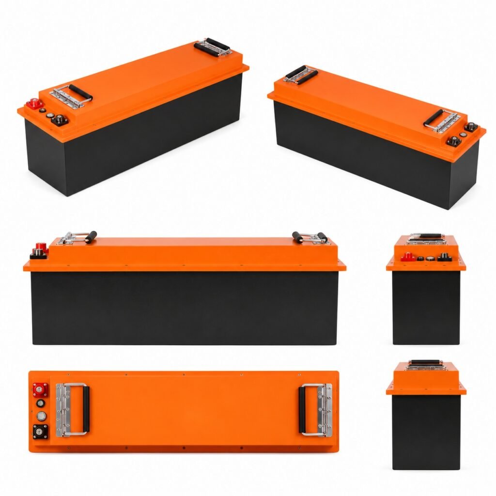
For the same power, a 24V system carries roughly half the current of a 12V system before losses. That can reduce cable and connection stress, but only when the inverter, charger, DC loads and protection devices are designed for 24V.
Voltage selection should be made at system level. Connecting the wrong load or charger can damage equipment even when the battery capacity appears suitable.
Buyers defining the initial scope can compare these requirements with HMX’s 12V LiFePO4 batteries. The page is a product or project reference; final suitability still requires a written project specification.
Power and energy must remain separate in low-voltage systems. The home battery sizing guide provides a load-schedule method that can be reused here before voltage, conductor and inverter limits are selected.
Direct answer: List every DC device and its allowed voltage before choosing the battery bank. Then calculate maximum current for inverter load, charging and fault protection.
Research review date: 30 September 2026. Quantitative statements are tied to the linked source and should be rechecked if procurement occurs later.
The technical comparison should also be checked against IEC 62619:2022 scope. IEC 62619:2022 covers safety requirements and tests for secondary lithium cells and batteries used in industrial applications, including stationary and motive uses.
Convert load power into current and voltage drop
For Backup-power, marine, RV and small solar distributors, the first task is to turn the intended service into measurable inputs and acceptance limits. The following table keeps the decision tied to evidence instead of a broad product label.
| Factor | 12V system | 24V system |
|---|---|---|
| Current at equal power | Higher | About half before losses |
| Common use | Lower-power DC and legacy 12V equipment | Higher-power small systems and 24V equipment |
| Cable impact | Larger conductor may be needed | Lower current can simplify long runs |
| Inverter/charger | Must be 12V compatible | Must be 24V compatible |
| Expansion | Follow approved parallel rules | Follow approved parallel rules |
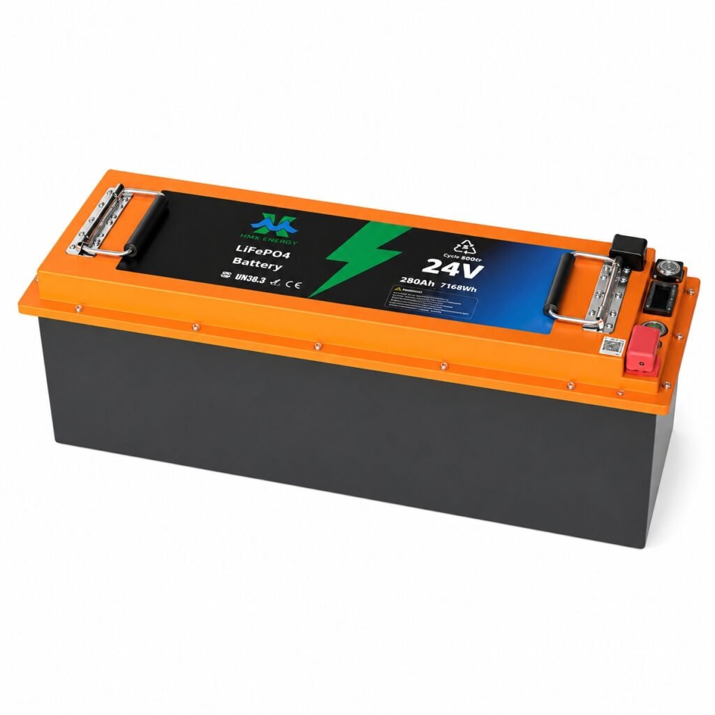
For a concrete equipment-level review, apply the checks above to the 24V LiFePO4 batteries and request confirmation for the intended site conditions and operating mode.
For specification and acceptance work, UNECE Manual of Tests and Criteria, Revision 8 provides an independent reference. UNECE publishes the current Manual of Tests and Criteria and its 2025 amendment, including changes affecting subsection 38.3 for lithium cells and batteries.
Low-voltage design pain is usually high current
These are the practical objections and failure modes most likely to stop approval, delay commissioning or create an avoidable service call for Backup-power, marine, RV and small solar distributors.
- A 12V choice creates cable, fuse and voltage-drop problems at the required power.
- Legacy accessories are not checked before moving to 24V.
- The charger profile and low-temperature charging protection are assumed.
Questions the buyer should ask before approval
- What maximum current flows at minimum battery voltage?
- Which existing loads require a converter or replacement?
- Where are branch protection and isolation located?
Set conductor, fuse and inverter limits from the current
The commercial offer should state its assumptions, exclusions and measurement boundary. Buyers can then compare systems on the same basis and keep later design changes under document control.
| Design check | Calculation or evidence | Risk controlled |
|---|---|---|
| Continuous current | Load watts divided by operating voltage and efficiency | Cable and BMS heating |
| Voltage drop | Length, conductor and current | Low-voltage trips |
| Fuse or breaker | DC rating and interrupt capacity | Cable fault protection |
| Charge profile | Approved voltage and current | Overcharge or nuisance trip |
| Terminal torque | Manufacturer value and inspection | Hot connections |
Action points for the project team
- Use DC-rated protection devices.
- Avoid drawing 12V accessories from only part of a 24V bank.
- Place over-current protection near the source as the design requires.
- Recheck cable temperature and voltage drop at full load.
Before design freeze, the project team should review IEC 60529 IP Code. IEC 60529 is the reference for enclosure ingress-protection classifications. An IP rating describes tested enclosure protection; it does not by itself approve an installation site.
Choose voltage from power, current and legacy loads
Calculate current at minimum operating voltage for each major load, not only at nominal voltage. Use cable length, permitted voltage drop, installation method and protective-device coordination to compare 12V and 24V architectures. Higher current can drive larger conductors, warmer terminations and greater sensitivity to connection resistance.
The same evidence and acceptance questions can be used when assessing HMX’s 24V 200Ah LiFePO4 battery; catalogue information should be reconciled with the controlled quotation and drawings.
Inventory pumps, lights, electronics, chargers, alternators and inverters already on the system. Moving to 24V may reduce current but require converters or equipment replacement. Remaining 12V branches need appropriately sized conversion and protection rather than an informal centre tap across part of a battery bank.
For the final evidence review, use U.S. DOE BESS procurement checklist as a source check. The U.S. Department of Energy checklist separates early project development, technical specifications and interconnection work for commercial lithium-ion systems.
Confirm charger profile, low-temperature charge protection, BMS current and load cutoff behaviour. Provide branch fuses, a main disconnect and clear polarity labels. Commission under representative load and measure voltage at the battery and farthest critical device to verify the design calculation.
From analysis to an auditable decision
- Calculate worst-case current and voltage drop.
- List every existing voltage-sensitive load and charging source.
- Select cables, protection, conversion and isolation equipment.
- Measure operating voltage under representative load.
Leave a serviceable low-voltage system record
Low-voltage systems are often modified after installation, so the owner needs an as-built record that makes conductor, fuse and battery-bank decisions visible. Document every branch, operating voltage, expected current and isolation point so later additions are reviewed against the original limits.
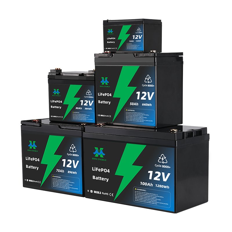
A related HMX reference is the 12V and 24V LiFePO4 range. Use it to frame the next supplier discussion, then record project-specific deviations before ordering.
- Battery topology, approved pack count and charger or inverter settings.
- Cable sizes, lengths, protection ratings and calculated voltage drop.
- Branch labels, isolation procedure and measured commissioning values.
- Rules for adding, replacing, balancing or removing battery packs.
Attach the record near the equipment where practical and keep a controlled digital copy. Future technicians should be able to identify the design limit before adding a load or another battery branch.
Decision Rule
Choose the option that satisfies the site conditions, service objective and maintenance model with the clearest test evidence. A larger nameplate or broader marketing claim is not a substitute for fit.