
PV inverter DC oversizing can be a valid design choice, but an array-to-inverter power ratio is not an electrical approval. A larger array may improve generation outside peak sunlight while the inverter limits output at other times. That does not permit excessive string voltage, an unapproved short-circuit current or a configuration outside the manufacturer’s allowed PV power.
For a hybrid system, the review is more complicated because PV energy may serve AC loads and charge a battery through different conversion paths. The battery cannot always absorb the surplus: it may be full, temperature-limited, unavailable or restricted by the charge controller. Evaluate the system architecture before making a claim about recovered clipping energy.
Keep the DC-to-AC ratio separate from the acceptance limits
Use a clear definition in the design report: DC-to-AC ratio equals the PV array’s rated DC power divided by the inverter’s rated AC output power. Specify the rating conditions and the equipment included in each total. A ratio based on the whole installation can hide an overloaded tracker on one inverter.
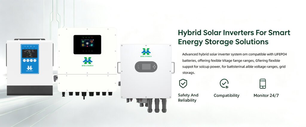
When reviewing the HMX solar inverter range, request the exact model’s permissible PV array configuration and per-input limits. A product family’s headline AC rating is not enough to approve a string design. Record the manual revision, module model and actual connection arrangement.
| Parameter | Question it answers | Evidence required |
|---|---|---|
| Permitted PV array power | How much rated module power may be connected? | Model-specific manufacturer allowance and conditions |
| Maximum DC voltage | Will the string remain below the absolute input limit? | Temperature-corrected voltage calculation and design rules |
| MPPT operating range | Can the tracker operate effectively across expected conditions? | String operating-voltage assessment |
| Operating input current | When might current limiting affect output? | Per-tracker and per-connection ratings |
| Allowed short-circuit current | Is the proposed array acceptable at the input? | Corrected current assessment and manufacturer’s limits |
| Thermal output limits | How does installation temperature affect available power? | Applicable derating information and site conditions |
As an equipment-specific example, the Fronius Symo GEN24 operating instructions present separate input and operating characteristics. Their values and permitted arrangements apply to those products, not to HMX inverters. The useful procurement habit is to seek the same separation of parameters in the proposed model’s documents.
Clipping describes a loss mechanism, not every flat output trace
A flattened power curve can result from an AC output limit, a site export limit, a controller command or temperature-related reduction. Current limiting and operation outside the MPPT range can create other losses. Those events need different remedies, even if the customer’s monitoring screen looks similar.
The System Advisor Model’s detailed PV result definitions distinguish AC power-limit clipping, MPPT voltage-limit losses and inverter thermal derating. Those model outputs are useful categories for analysis, not proof that a real installation experienced a particular fault.
Compare PV input conditions, AC output, equipment temperature, grid conditions and active commands at matching timestamps. A total daily energy figure cannot identify which limit operated. Keep modelled losses separate from observed events, and do not describe an unmeasured loss as a known percentage.
| Observed limitation | What to check | What not to conclude immediately |
|---|---|---|
| Output near the AC rating | Available DC power, output boundary and other active limits | That every flat interval is ordinary clipping |
| Reduced output during hot conditions | Equipment temperatures, ventilation and derating status | That additional modules will fix the problem |
| One tracker underperforming | String layout, current limits, shading and operating voltage | That the installation-wide DC-to-AC ratio is the cause |
| Output follows export permission | Meter readings and controller commands | That the inverter is undersized |
| Battery stops taking energy | Charge permission, state of charge and active charge limits | That PV input capability has disappeared |
Review the hybrid energy paths before promising clipping recovery
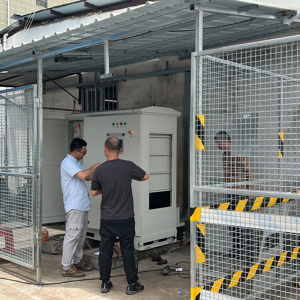
A DC-coupled battery may provide a route for PV energy that would otherwise exceed the AC conversion limit, if the equipment supports that operation. It cannot recover energy that was unavailable because of an unacceptable string design, shading or an upstream constraint. The usable route depends on the product architecture and the operating state.
For the CHMG055 16 kW inverter option, obtain the model-specific simultaneous PV, AC and battery power capabilities before making a system proposal. Do not add headline ratings together and assume the sum is available continuously. Clarify whether a published limit is a shared conversion constraint or a limit on a separate path.
Model the battery’s usable charge window and dispatch policy. A battery that is already charged before the solar peak may provide little room for additional energy during that peak. Conversely, deliberately creating charge headroom may affect backup readiness. Treat that trade-off as an operating decision, not as free extra yield.
Use time-series modelling, then check the model’s resolution
The value of additional modules depends on weather, roof orientation, shading, the load profile and the project’s permitted energy destinations. Compare candidate layouts using a consistent weather dataset and explicit assumptions. An annual energy total should be accompanied by the timing of generation and losses, especially where export or battery charging is constrained.
SAM’s subhourly clipping-loss documentation notes that power limiting within an hour can be missed by an hourly average. That matters when a proposal relies on small differences between designs. Record the modelling time step and the treatment of clipping; do not present extra decimal places as evidence of greater certainty.
For an integrated solar and storage system, retain the battery dispatch assumptions with the PV model. Changing reserve policy or charge permission after commissioning can change the energy result without any change to the module array.
Approve three different decisions
The electrical review must confirm the array is permitted. The energy review must explain when additional production will be useful. The commercial review must use actual project costs and tariffs to assess the value. Passing one does not automatically pass the others.
The final design file should contain the string calculations, per-tracker allocation, manufacturer approval conditions, modelling assumptions and operating policy. If a proposal gives only a preferred DC-to-AC ratio, the most important review work is still missing.